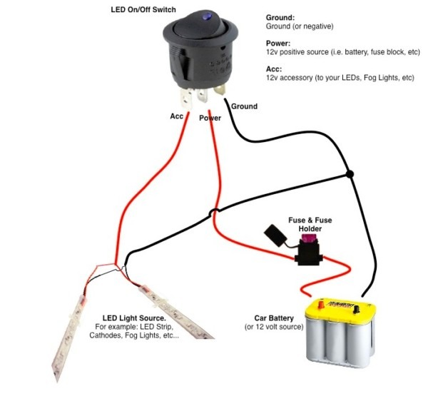
12v Switch Wiring Diagrams are essential tools for anyone working on electrical systems in vehicles, boats, or other machinery. These diagrams provide a visual representation of how the electrical components are connected and how they interact when the switch is turned on or off. Understanding how to read and interpret these diagrams is crucial for successful installations, repairs, and troubleshooting.
Why are 12v Switch Wiring Diagrams essential?
- Ensure proper connection of electrical components
- Prevent electrical shorts or malfunctions
- Guide troubleshooting efforts
- Comply with safety standards
How to read and interpret 12v Switch Wiring Diagrams effectively
- Identify the power source and ground connections
- Follow the flow of current from the switch to the components
- Understand the symbols and labels used in the diagram
- Refer to the legend or key for additional information
Using 12v Switch Wiring Diagrams for troubleshooting electrical problems
- Identify potential issues with connections or components
- Trace the flow of current to pinpoint the source of the problem
- Compare the diagram to the actual wiring for discrepancies
- Test components and connections for continuity or voltage
When working with electrical systems and using wiring diagrams, safety should always be a top priority. Here are some important safety tips and best practices to keep in mind:
- Always disconnect the power source before working on any electrical system
- Use insulated tools and equipment to prevent shock hazards
- Avoid working in wet or damp conditions to reduce the risk of electrocution
- Double-check all connections and wiring before turning on the power
- If you are unsure or uncomfortable with any aspect of the wiring, seek professional help
12v Switch Wiring Diagram
Simple 12 Volt Switch Wiring Diagram

Wiring Diagram For 12v Relay And Switch

Switch Wiring Diagram 12v
12 Volt Light Switch Wiring Diagram

12v Switch Wiring Diagram

12v 2 Way Switch Wiring Diagram – Wiring Diagram
