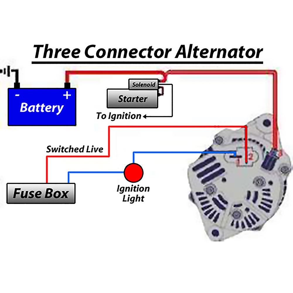
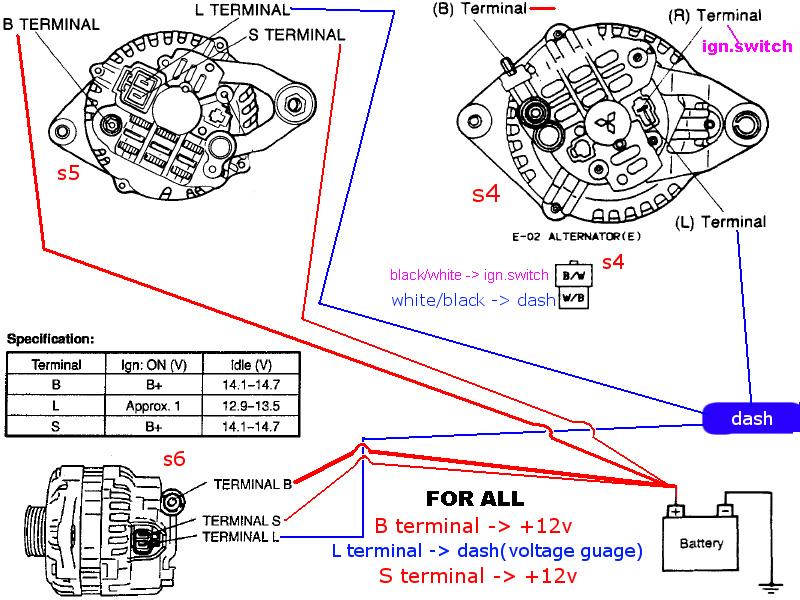
Alternator Wiring Schematic is a crucial component in understanding the electrical system of a vehicle. It provides a detailed diagram of the wiring connections and functions of the alternator, allowing mechanics and technicians to troubleshoot and repair electrical issues effectively.
Why Alternator Wiring Schematic are essential
- Helps in understanding the wiring connections of the alternator
- Assists in diagnosing electrical problems in the vehicle
- Guides in the proper installation of the alternator
- Ensures the correct functioning of the electrical system
How to read and interpret Alternator Wiring Schematic effectively
Reading an Alternator Wiring Schematic may seem daunting at first, but with a little practice, it becomes easier. Here are some tips to help you interpret the schematic effectively:
- Study the key or legend provided in the schematic to understand the symbols used
- Follow the wiring diagram from the source to the destination to trace the electrical flow
- Pay attention to color-coding and numbering of wires for easy identification
- Identify components and their connections to understand the overall circuit
How Alternator Wiring Schematic are used for troubleshooting electrical problems
Alternator Wiring Schematic play a vital role in troubleshooting electrical issues in a vehicle. By following the schematic and performing tests, you can pinpoint the root cause of the problem. Here’s how you can use the schematic for troubleshooting:
- Check for continuity in the wiring connections to ensure proper electrical flow
- Verify voltage levels at different points in the circuit to identify any voltage drops
- Inspect the components connected to the alternator for any signs of damage or malfunction
- Compare the actual wiring with the schematic to detect any discrepancies or errors
When working with Alternator Wiring Schematic or any electrical systems, it is crucial to prioritize safety. Here are some safety tips and best practices to keep in mind:
- Always disconnect the battery before working on the electrical system to prevent electric shock
- Use insulated tools to avoid short circuits and electrical hazards
- Wear protective gear such as gloves and goggles to protect yourself from potential accidents
- Follow the manufacturer’s instructions and guidelines when handling electrical components
Alternator Wiring Schematic
Common Delco SI Series Alternator Wiring Diagram | Smith Co Electric

24 Volt Alternator Wiring Diagram

fd alternator wiring – RX7Club.com

Alternator Schematic Diagram – Headcontrolsystem

Denso Alternator Wiring Schematic – Wiring Library – 12 Volt Alternator

[2 Wire, 3 Wire, and 4 Wire] Alternator Wiring Diagram – Drill and Driver
![Alternator Wiring Schematic [2 Wire, 3 Wire, and 4 Wire] Alternator Wiring Diagram - Drill and Driver](https://i1.wp.com/www.drillanddriver.com/wp-content/uploads/2022/12/How-Does-An-Alternator-work-1024x626.png)