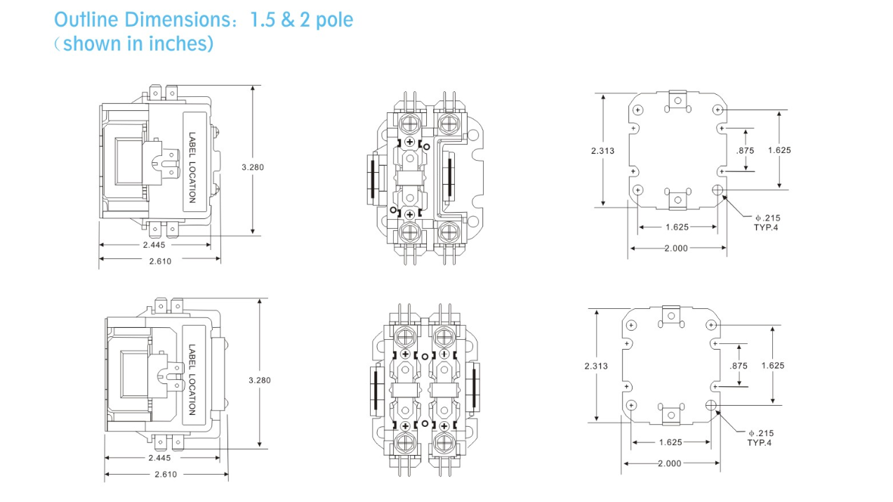
Definite Purpose Contactor Wiring Diagrams are essential tools for anyone working with electrical systems. These diagrams provide a visual representation of the electrical connections within a definite purpose contactor, helping users understand how the various components are interconnected.
Importance of Definite Purpose Contactor Wiring Diagrams
- Ensure proper installation of electrical components
- Aid in troubleshooting electrical issues
- Prevent electrical malfunctions and hazards
Reading and Interpreting Wiring Diagrams
When reading a definite purpose contactor wiring diagram, it is important to pay attention to the symbols and labels used. Each symbol represents a specific electrical component or connection, and understanding these symbols is crucial for interpreting the diagram accurately.
Key components to look for:
- Contactors
- Coils
- Control circuits
- Power supply connections
Using Wiring Diagrams for Troubleshooting
Definite purpose contactor wiring diagrams are invaluable for troubleshooting electrical problems. By referencing the diagram, users can quickly identify the source of an issue and make the necessary repairs or adjustments.
Common troubleshooting scenarios:
- No power to the contactor
- Incorrect wiring connections
- Malfunctioning components
Safety Tips for Working with Electrical Systems
When working with electrical systems and using wiring diagrams, it is essential to prioritize safety. Follow these tips to ensure a safe working environment:
- Always turn off power before working on electrical systems
- Use insulated tools to prevent electric shock
- Avoid working on electrical systems in wet or damp conditions
- Wear appropriate personal protective equipment, such as gloves and safety goggles
Definite Purpose Contactor Wiring Diagram
How to Wire an Eaton Definite Purpose Contactor: A Step-by-Step Wiring

How To Connect A Contactor Diagram – Wiring Draw And Schematic
Contactor Coil Wiring Diagram

Understanding The Basics Of 240 Volt Contactor Wiring Diagrams – WIREGRAM

30 Definite Purpose Contactor Wiring Diagram – Wire Diagram Source

Square D 8910 Dpa 43 Wiring Diagram – Art Mark
