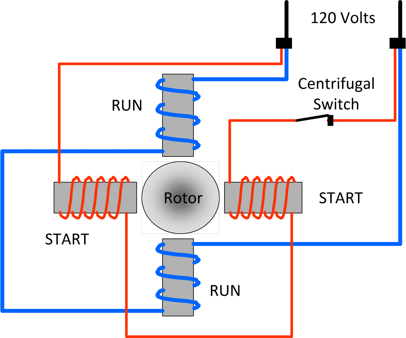
Electrical Motor Wiring Diagrams are crucial tools for mechanics and electricians when working with electrical motors. These diagrams provide a visual representation of the connections and components within the motor, helping to ensure proper installation and troubleshooting. Understanding how to read and interpret these diagrams is essential for anyone working with electrical systems.
Why are Electrical Motor Wiring Diagrams Essential?
Electrical Motor Wiring Diagrams are essential for a number of reasons:
- They provide a visual guide for wiring connections, helping to prevent mistakes during installation.
- They show the relationship between different components within the motor, allowing for easier troubleshooting.
- They help ensure compliance with safety standards and regulations.
How to Read and Interpret Electrical Motor Wiring Diagrams
Reading and interpreting Electrical Motor Wiring Diagrams may seem daunting at first, but with some guidance, it becomes much easier:
- Start by familiarizing yourself with the symbols and conventions used in the diagram.
- Identify the main components of the motor, such as the rotor, stator, and various electrical connections.
- Follow the lines and connections in the diagram to understand how power flows through the motor.
- Pay attention to any labels or annotations that provide additional information about specific components.
Using Electrical Motor Wiring Diagrams for Troubleshooting
Electrical Motor Wiring Diagrams are invaluable tools for troubleshooting electrical problems:
- By comparing the actual wiring of the motor to the diagram, you can pinpoint any discrepancies that may be causing issues.
- You can use the diagram to trace the flow of power and identify potential areas of concern, such as faulty connections or components.
- Following the diagram step by step can help you systematically diagnose and fix electrical problems in the motor.
Importance of Safety When Working with Electrical Systems
When working with Electrical Motor Wiring Diagrams and electrical systems in general, safety should always be the top priority:
- Always turn off the power supply before working on any electrical equipment.
- Use insulated tools and equipment to prevent electric shock.
- Wear appropriate personal protective equipment, such as gloves and safety goggles.
- Double-check all connections and wiring before turning the power back on to avoid potential hazards.
Electrical Motor Wiring Diagram
Wiring Single Phase Motor

⭐ 220V Single Phase Motor Wiring Diagram 👈 – JAN19 stampninclady

Electrical Motor Wiring Diagram

Motor Wiring Diagram Single Phase

Schematic vs. Wiring Diagrams – Basic Motor Control

3 Phase Motor Wiring Explained
