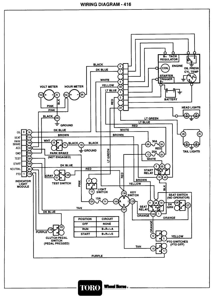
When it comes to troubleshooting electrical problems in Toro equipment, having a clear understanding of the Toro Ignition Switch Wiring Diagram is essential. This diagram serves as a roadmap for the electrical system of your Toro machine, helping you identify and resolve any issues that may arise.
Why Toro Ignition Switch Wiring Diagrams are Essential
Understanding the Toro Ignition Switch Wiring Diagram is crucial for several reasons:
- Helps in identifying the various components of the electrical system
- Guides in tracing the flow of electricity through the system
- Aids in diagnosing and troubleshooting electrical problems effectively
Reading and Interpreting Toro Ignition Switch Wiring Diagrams
When reading a Toro Ignition Switch Wiring Diagram, it’s important to keep the following in mind:
- Each wire is represented by a specific color code
- Components are labeled for easy identification
- Lines indicate the connections between different components
Using Toro Ignition Switch Wiring Diagrams for Troubleshooting
Toro Ignition Switch Wiring Diagrams can be invaluable when troubleshooting electrical problems. By following the diagram, you can:
- Locate the source of the issue within the electrical system
- Check for continuity and proper connections
- Identify any faulty components that may need replacement
Importance of Safety
Working with electrical systems can be dangerous if proper precautions are not taken. Here are some safety tips to keep in mind when using Toro Ignition Switch Wiring Diagrams:
- Always disconnect the power source before working on the electrical system
- Use insulated tools to prevent electric shocks
- Avoid working in wet conditions or with wet hands
- If you’re unsure about a particular task, seek help from a qualified professional
Toro Ignition Switch Wiring Diagram
Toro 244-h Ignition Wiring Diagram

Toro Ignition Switch Wiring Diagram- All In One Details!

Toro 244-h Ignition Wiring Diagram

Understanding The Toro Ignition Switch Wiring Diagram – Moo Wiring

Toro 244-h Ignition Wiring Diagram

Scott Wired: Ignition Switch Wiring Diagram Toro Zero Turn Down
